Utility Capacitor Bank Switch Failure Investigation
 By: Tom Grebe, Principal Consultant
tgrebe@enernex.com
865-770-4880
![]()
Power system apparatus, such as switchgear, capacitor banks, and surge arresters may be exposed to various types of transients. Transients from restrikes during vacuum switch opening may cause problems for electrical equipment because they can cause local overstressing of the insulation system and exceed surge arrester energy ratings. Capacitor bank switch restrikes often produce high transient voltage surges that result in severe energy duties for adjacent arresters or damage unprotected equipment.
A transient investigation was completed for a utility in Kansas. The primary purpose of the study was to investigate a capacitor bank vacuum switch failure that occurred during a multiple restrike event on an ungrounded 7,800 kVAr, 34.5kV capacitor bank that was protected with a 27kV MOV arrester. A large number of customer power quality complaints recorded during the capacitor bank switch failure included adjustable-speed drives (ASDs) and HVAC equipment tripping due to the resulting secondary transient overvoltages.
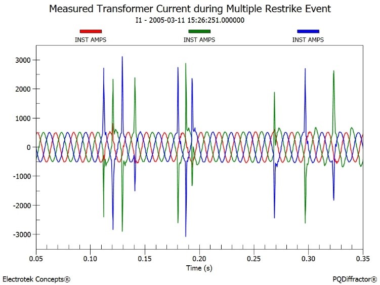
The principal objectives of the study were to determine transient overvoltages and evaluate mitigation alternatives for vacuum switch restrike transients (refer to Figure 1) that were believed to have caused the capacitor bank switch failure. The transient analysis for the study was completed using the PSCAD®/EMTDC® simulation program.
A capacitor bank switching device de-energizes a capacitor bank at a current zero. Since the current is capacitive, the voltage at the time of current interruption is at a system peak. Successful interruption depends on whether the switch can develop sufficient dielectric strength to withstand the rate-of-rise and the peak recovery voltage. For grounded-wye capacitor banks, two times (2.0 per-unit) the system peak voltage will appear across the switch contacts one-half cycle after interruption. If the switch cannot withstand this recovery voltage, the switch will restrike.
During normal grounded-wye capacitor bank de-energization, the capacitor bank current is interrupted at the peak system voltage thus leaving a 1.0 per-unit trapped charge on the capacitor bank. This trapped charge results in an offset in the transient recovery voltage that reaches a magnitude of 2.0 per-unit one-half cycle after opening. Significant transient voltages can occur if the switch restrikes during clearing. The worst restrike transient occurs when twice the system peak voltage appears across the switch contacts. Theoretically, in this case, the magnitude of the transient voltage approaches 3.0 per-unit.
The transient voltages on a capacitor bank and the recovery voltages across the switch can be reduced by installing arresters on the capacitor bank side of the switching device. If the switch is rated for the recovery voltages involved, then the arresters can be located on either the capacitor bank side or source side of the switch. Connecting arresters line-to-ground on an ungrounded-wye capacitor bank does not necessarily limit the voltages trapped on the capacitor units to the arrester’s protective level.
Since a restriking capacitor bank switching device can result in transient voltages that may result in severe arrester energy duty or equipment damage, it is desirable to choose a switching device that will minimize the possibility of restrike. Since all switching devices have some probability of restrike, the effects of restrike events should be considered.
The Power System Engineering group at EnerNex has extensive expertise performing power system studies investigating the transients associated with vacuum switch operations. These studies often require use of sophisticated digital simulation tools (e.g., EMTP-RV, PSCAD). Computer simulations provide a convenient means to characterize transient phenomena, determine resulting problems, and evaluate possible mitigation alternatives.
Figure 1 – Measured Transformer Secondary Current during Capacitor Bank Vacuum Switch Failure